VNR File Assembler
NAND controllers write data to memory chips by logical blocks in mixed order. Therefore, recovering files from such mixed dumps would fail as files may begin in one block and continue in another that is located somewhere else, not necessarily after. As a result, files larger than one logical block will not be recovered, and the file system will not be available. That is why arranging mixed blocks into logical order- the same as they were located in a logical image, is the last step of data recovery from NAND memory-based devices. After that, big files can be recovered, and the file system may be available. However, there are cases where is not possible to arrange the blocks in logical order, and the VNR File Assembler is the tool specially designed to recover fragmented files from such cases. It scans all the blocks looking for fragments of the files and then puts together appropriate blocks.
The second scenario where the File Assembler may be used is when there are big fragmented files (e.g., video files), and the file system is lost or damaged, making the allocation of the big files unknown. In this case, regular carving (raw recovery) provides only damaged files.
The VNR File Assembler provides a completely new approach to such cases, utilizing three advanced technologies. In this article, we will provide an overview of the tool and guide you through the process of using it to recover data.
Technologies
The Rusolut File Assembler utilizes three technologies to recover data:
1. File System Metadata and File Attributes Analysis:
This technology analyzes remains of file system metadata and file attributes, using advanced methods to determine logical block numbers and assemble the original file structure. The software supports the following file systems: FAT16, FAT32, exFAT, and NTFS.
2. ZIP Archive Internals Assembly:
This technology scans the internal components of ZIP container files and recreates the original archive structure. It is useful for recovering fragmented office files, which are essentially ZIP archives, including: DOCx, XLSx, PPTx, ODT, ODS, ODP, and ZIP.
3. Intelligent Visual Content Analysis of Multimedia Files:
This is the flagship technology of the VNR File Assembler. It gathers all fragmented multimedia file pieces from the whole dump and then performs intelligent visual content analysis of those fragments. After that, it assembles files based on the images shown there. It is like manually assembling a puzzle by checking each and every picture and video fragment in a dump.
Assembling Modes
As mentioned earlier, the File Assembler is useful for cases with mixed logical blocks and for cases with arranged blocks (normal logical images) but with an unavailable file system and big fragmented files. The mixed blocks mode should be selected for the first type of cases, and the arranged blocks mode for the second type. There are more details about those modes below.
Mixed Blocks Mode:
This mode assembles files by logical blocks. It is designed for cases such as Toshiba and SSS devices, where block translation is not possible because logical block numbers are missing in the spare area. The block size for assembling is indicated in the field "Block size w/o SA" (Block size without Service area). The block size with Service Area is necessary for Virtual Block Table creation. Both of these values are set automatically in most cases.
Arranged Blocks Mode:
This mode assembles fragmented files by clusters from dumps with arranged logical blocks (logical images). It is useful when a proper logical image is assembled, but the file system is corrupted or missing, and the dump contains large fragmented files, for example, data recovery from formatted memory cards from video cameras with a lost file system.
Supported File Formats
The table below demonstrates the supported File Formats and appropriate Assembling modes for them.
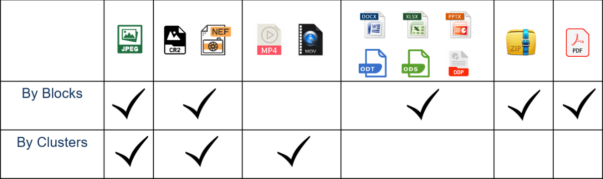
ZIP and PDF files are assembled by Blocks only. Pictures could be assembled by Blocks and by Clusters. And the Video files are assembled by clusters only.
File System Selection
When using the File Assembler, it is important to select the correct file system if it is known. By selecting the correct file system, the tool will ignore any other unnecessary file systems on the storage device during analysis. This will help to improve the accuracy and efficiency of the analysis by focusing only on the relevant file system. If there is no information what file system was used on a device, then the Unknown option should be selected.
Assembling options
Basic Scan
During this scan, the assembler gathers information about all file fragments and file system remains from the entire dump for all further analyses. It also creates a block table XML file that can be uploaded to the Markers table element in order to recreate the original file system.
ZIP analysis
Fragmented and Unfragmented ZIP based files: ZIP archives, Microsoft Office files, Open Office files are recovered on this Scan.
Pictures by Blocks
Fragmented and Unfragmented pictures are assembled BY LOGICAL BLOCKS on this stage.
Pictures by Clusters
Fragmented and Unfragmented pictures are assembled by CLUSTERS.
Video by Frames
Video files are recovered by frames on this scan.
Depending on the selected assembling mode, different sets of scans are available. The Mixed Blocks mode allows running both scans for pictures. In this case, pictures will be assembled by blocks first and then the ones that are still fragmented will be assembled by clusters. This mode should be used for mixed dumps such as Toshiba, SSS, and similar.
The Arranged Blocks mode allows running picture assembling by clusters only. This mode should be used for logical images only, where it is necessary to recover fragmented files by file system files. It could be useful for cases with big raw format pictures when the file system is not available.
Scan Results
In the scan results section, you can save the results of an analysis to load it later. This feature allows you to avoid another analysis if you need to close or restart a task and save valuable time.
Use Cache File
The Use Cache File option is recommended when the analysis is performed on the Logical image element and there are complex transformations before it. In this case, the tool will make a copy of the logical dump on the Basic scan and then use that cached image during all subsequent passes. It is recommended to use a good SSD drive for the Cache storage to ensure optimal performance.
However, if you run the analysis straight on a dump stored on fast storage, then there is no sense in making a copy of this dump in cache, and the option should be disabled. This will ensure that the analysis runs efficiently and quickly without unnecessary data duplication.
Marking of recovered files
Unfragmented- Initially unfragmented files are placed in this category.
Bi-fragmented- Good recovered files that consisted of two fragments are placed here.
Fragmented- Good recovered files that consisted of more than two fragments are placed in this category.
Bit Errors- Unfragmented pictures with Bit errors.
Unrecoverable- Files that are not possible to assemble.
The results of Assembler work
1. Files
2. Assembler results.xml
A “save” file with all the results off the Assembler work that is created after the Assembler finished all procedures. It can be uploaded later to restore the scan results.
3. Assembler block table.xml
A block table that could be uploaded to the markers table element in order to recreate an original file system.
Case studies.
Case 1. Toshiba controller with no LBN in the Service Area.
The solution for this particular case is quite simple- only XOR and ECC should be applied,
but due to the absence of the LBN in the service area, it is not possible to arrange logical blocks in ascending order. The file carver, which ran on the data area element (that removes the service area from the physical dump), shows quite poor results because blocks are still mixed, so files are fragmented.
At the same time, the VNR assembler, which ran on the same element, produces much better results. It recovers 283 good pictures versus 190 recovered with the standard raw recovery.
Case 2. Formatted SD card from SONY A73 camera
This is a fairly common case where someone accidentally performs a quick format of an SD card in their camera. As a result, any logical recovery software can recover nothing because the card appears to be completely formatted and filled with zeroes. However, if we bypass the controller and read the physical dump via the NAND interface, we discover that the card is still full of data. Therefore, with a chip-off approach, it is possible to retrieve the data and obtain a logical image with the original video files inside. Nevertheless, although the files are present in the image, they are still inaccessible because the original file system has been overwritten by a new one, which is essentially empty.
Even when a Raw recovery is executed using popular logical recovery software, the results are not satisfactory. Although the blocks are arranged in logical order, the files are still fragmented due to their large size.
On the other hand, the VNR File Assembler is able to recover 365 video files from the same dump.
Related Articles
Different Page Layouts in Devices with CBM Controllers
It is a rare situation, but sometimes in CBM-controlled devices with bad columns, we encounter a problem where the ECC does not fit perfectly. The best way to explain this issue is through a real-world case. In the example below, the chip has 4 ...Phison dynamic XOR
Majority of NAND memory devices that use scrambling algorithms generate their XOR keys statically. When a user writes new data to the NAND chip, the controller transforms this data with the XOR key that is generated every time with the same binary. ...Silicon Motion(SM) controllers - Data recovery
We can find plenty of NAND controllers on the market and without any doubt one of the most popular is SiliconMotion. These controllers found their use in all kinds of flash devices, starting from USB flash drives, SD cards, monolithic devices, and ...VNR Silicon Motion AI XOR
When you work with devices based on modern Silicon Motion controllers, it is essential to separate a dump by planes. Before separating the planes, it's necessary to determine how many planes exist per crystal/dump. There are two methods to verify the ...Asymmetric Multi-Plane Page Allocation – Rebuilding the Logical Image
Many modern NAND flash controllers, including those made by Phison, Silicon Motion, and others, use a method called asymmetric multi-plane page allocation. In most cases, logical blocks are built in the standard way. However, some blocks are created ...