Block extraction
Video tutorial
Introduction
In this little tutorial the procedure of block extraction is briefly explained. Blocks are second most basic structures in NAND memory dumps and their length defines (in most cases) length of XOR key, for this reason it is essential to know the length of single block to solve any case. Finding substructures of dump is not always an easy job, and sometimes comparing blocks might come with help as a solution or at least a clue, about how data was allocated. That is why block extraction is an important skill in data recovery case solving.
Detecting blocks
Let's assume that user already has dump to work with and knows everything about dump structures, so page length and block size are known. First thing the user has to do is find a block which is somehow interesting to work with (e.g. it has clear XOR key to extract).
Fig.1. Bitmap in Dump viewer of Visual Nand Reconstructor.
To see edges of blocks user must click on a Highlight blocks button. This option allows easy recognition of single blocks in bitmap, and helps in many situations when working with dump in VNR.
Fig.2. Block boundary with Highlight blocks.
Area selection 1
After highlighting blocks user have to find first bit of the block that is to be extracted and select it by clicking LMB (left mouse button) on this bit. LMB click places beginning marker (red cross) in bitmap. Zooming in (mouse roller forward) and out (mouse roller backward) might help to select the right point. Right mouse button (RMB) places second marker (pink cross) which defines end of selected area. This way of defining extraction site might be not very precise. That's where second way of selecting block end comes into play.
Fig.3. Block's first bit selected with LMB click.
Fig.4. Block's last bit selected with RMB click.
Area selection 2
Even if user experiences problems with mouse clicking on right bits, it is still easy to set exact block size and address in extraction tool. First, user has to select with LMB any bit of block before the interesting one. Then proceed to Navigator tab on toolbar.
Fig.5. Navigator tab in Dump viewer's toolbar.
In section Blocks user has to click on green button with letter 'B' next to field Block size. After clicking, this field will contain numerical value which represents block size in bytes.
Fig.6. Defined value in Block size field.
Then, to perfectly place red marker on a beginning of interesting block, user has to press the arrow-with-bar button, located on the left of Block size field. This action will move start marker exactly to the beginning of next block (which is the interesting one in this case). And this is all about right placing the markers.
Extraction
When user is done with selecting area, or at least placed beginning marker in the right place, the procedure for extraction is almost done. Next step is to go to Workspace and click on Extract area button that can be found in the upper-left corner of VNR window.
Fig.7. Location of Extract area button.
This will invoke small window with several settings.
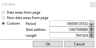
Fig.8. Cut area window.
In this window user selects option Custom (if not selected by default). Last step is to check if Length field has correct value. In case of selecting just the beginning of block this the length is 1 (as in figure 8), however if user selected whole block, this value must be equal to block size. If it is not, then correction must be done.
Fig.9.a. Structure parameters from Workspace toolbar.
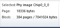
Fig.9.b. Corrected settings to extract single block.
Side note
At the point, where Lenght is being specified, user can in fact apply any value needed. E.g. three blocks from the case of figure 9. would be 3 × 7,041,024 bytes, which is 21,123,072 bytes, and setting this value as Length in configuration of Extract area will result in extraction from dump that has length of three blocks. This is how extracted area can be scaled up or down just by modifying Length value (fig.9.b).
Ending
After making sure, that all settings are right, and clicking 'Ok' in window from figure 9.b in Workspace appears new element Offsets, which performs extraction procedure. By opening Dump viewer by double-click on this element it can be seen, that dump at this point have been shortened to a size of one block (or any other size that user has defined). It does not affect physical image; Offsets does its job in real time and does not save or overwrite any data, so to preserve its dump user must save it manually. Left panel Parameters of Offsets that extracts single block should look like following.
Fig.10. Parameters of element Offsets with settings to extract single block.
This exact procedure (excluding automatic start point selection) might be applied in every case of selection. Single block extraction is presented because it is the essential procedure while XOR key extraction, however not always necessary because of built-in VNR XOR key database.
Related Articles
Phison - Double block rotation and SLC block management
The solution step by step It’s been many years since the first NAND controllers were released on the market. Many technological aspects of flash devices have changed since that time, but one thing is certain, along with the multiplied capacity, the ...Insert area, Skip area, Extract area
Sometimes some specific cases require a non-standard approach when it's necessary to extract, insert or skip some areas. For these cases, VNR has three designed functions. Each of this function allows to perform simple and cyclical operations on the ...Block Rotation element for Phison and Sandisk devices
The VNR has a user-friendly Block Rotation element, in almost all Phison and Sandisk cases that have rotation inside blocks. It is a simple way to reverse it. To make an element even easier to use, we will explain how to determine what kind of ...Flash Drive Data Recovery educational webinars
Chip-off NAND data recovery with Visual NAND reconstructor consists of several essential steps whose task is to reverse transformations which controller applied on user data. In those education webinars, you will find out how to extract raw dumps ...PS2251-09/19 XOR
On the market, it is possible to find many UFD devices based on the PS2251-09/19 controller family. Examples include: PS2251-09-V, PS2251-09-26, PS2251-19-26. Picture 01. Devices with these controllers After research, we decided to create a new ...